The main bearings of a two-stroke marine diesel engine support the crankshaft and absorb the heavy cyclic forces from combustion. Given the extreme working conditions, regular inspection and clearance monitoring are essential to prevent catastrophic crankshaft failure or bearing wipeouts.
1. Safety and Preparation
Before entering the crankcase or touching any moving components:
- Isolation: Lock out the starting air system, open all indicator cocks, engage the turning gear, and tag out power sources.
- Enclosed Space Entry: Thoroughly ventilate the crankcase, check atmosphere conditions ($O_2$ levels and hazardous gas presence), and issue an Enclosed Space Entry permit.
Cleanliness: Ensure all personnel wear clean PPE and non-linting coveralls to prevent dirt or debris from contaminating the lube oil system.
2. Preliminary Checks & Non-Intrusive Inspections
Modern engine manufacturers (such as MAN B&W and WinGD/Sulzer) recommend avoiding unnecessary opening of bearing shells unless an abnormality is detected.
- Crankcase Sump & Oil Filter Check: Visually inspect the bottom of the oil pan and lube oil discharge filters for metal flakes or fragments (white metal or aluminum alloys).
- Wire Feeler Test: Using a thin wire gauge, probe along the edge of the bearing shell inside the crankcase. If the wire catches or slips into a recess, it indicates material fatigue or flaking at the bearing edge.
- Crankshaft Deflection Measurement: Fit a dial deflection gauge between the crank webs for each cylinder. Take readings as the shaft is rotated to determine if uneven main bearing wear has caused alignment issues.
3. Measuring Bearing Clearances In-Situ
Because the heavy crankshaft rests on the bottom bearing shell, main bearing clearance is taken at the top shell.
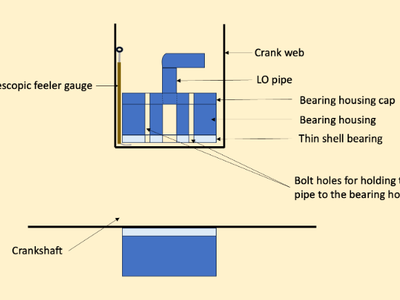
- Feeler/Telescopic Gauges: Insert a standard feeler gauge or specialized telescopic gauge between the top shell and journal pin. Record the reading and compare it with the engine builder's maximum limit.
Bridge Gauge & Depth Micrometer: For engines requiring upper keep removal (e.g., Sulzer designs), fit a bridge gauge over the journal and measure the distance from the bridge top to the journal pin.
4. Opening and Dismantling (If Overhaul or Damage Is Identified)